Saturday, December 8, 2012

ATX PSU Repair

As noted in the HTPC build I used a repaired Ultra D0408 ATX PSU. I was using it in the P4 and it would work fine for a long time, then just start randomly rebooting, then it would be fine again. At first I thought it was the motherboard or ram, but then discovered if i bumped the desk or case it would almost always start acting up. Of course that screams "Something's Loose!".

So I had the opportunity to remove it and inspect it as I did my upgrade. Here's what I found:

Caps all look ok, no bulges, etc.
Cover Off
Be very careful when taking these apart, Voltages may remain for a very long time. I held it by the wires to remove the board, flipped it over and checked those 2 big caps (upper left). They had less than 2VDC in them, but depending on the failure it could be over 300VDC.

Bottom of board
Now we can see something, I don't know if you can see it in the above picture but in the lower right corner there is a capacitor that has come loose from the solder. It is on the 12V rail. The heatsink on the left of the unit also has a bad solder joint, but it appears to be isolated.
Bad solder joint (about in center)
So I soldered it up and will try it out. These units are cheap, so it doesn't pay to spend much time fixing them, but sometimes it's something simple like this. It's also practice for things like the Parrallax. Time will tell if that was the problem or if it's something more serious.

HTPC & Home Server Build Part 1 - Hardware

I moved over the summer and I now get 14 Channels of free over the air TV (up from 3) and yet there's still nothing on. It seems all the good stuff is on when I'm busy (or sleeping). So I've been messing with MythTV on a old P4.

It worked pretty good except for a few drawbacks:
  1. It is kind of noisy.
  2. It's a bigger power hog than I anticipated. It consumes about 100W idle. I figured it out as costing me about $85/yr in electric. Not bad for my TV bill, but a little irritating too.
So I was looking around on black friday and found a nice little mini-ITX motherboard with 8GB of ram included for $65. It's no Phenom X6, but since it will spend a lot of time idle or under light loads I think it's a good fit.

Specs:
  • Biostar Deluxe A681-350 (AMD E-350 1.6GHZ Dual-Core APU)
  • 8GB of G.Skill Ripjaws X DDR3
  • Hauppauge WinTV HVR 950Q (may swap with a Sabrent TV-DGUSB eventually, but I have to re-compile a kernel module for that)
  • Salvaged 250GB Sata Drive (someday I'll upgrade to a 1-3TB Sata)
  • Salvaged ATX case
  • Repaired Ultra D0408 ATX PSU
  • Total idle power consumption measured at 40W
Biostar A681-350 and G.Skill Ripjaws X DDR3
Motherboard with ram installed
All Assembled
I'm still figuring what all I want it to do, so far I've got:
  • MythTV, that's the big one, the main purpose of the whole project.
  • File and Backup Server
  • Local web server for development, testing, etc.
I will do a series of posts covering the software installation and configuration eventually.

Curiously the my complete setup with the P4 consumed approximately 100W idle and 200W with the screen on. The new one consumes 40W idle and 100W with the screen on. I don't understand it, it's the same screen! Could the video card in the P4 detect the screen was off and power down? Would a video card consume nearly 50W? Is my Kill-A-Watt Broken? Tune in next week...

Saturday, October 27, 2012

Parallax 7345 SMPS Repair Tips

I started this as a reply in the Parallax 7345 RV Power Converter (SMPS) post. It quickly grew to the point I decided to tidy it up and make a new post out of it. Most of the specific info is for the Parallax unit though it may apply to other SMPS's.

Most of what I know about SMPS repair comes from reading: http://www.repairfaq.org/sam/smpsfaq.htm If you intend to work on a SMPS I strongly suggest reading and digesting the contents of it first.

Possible Problem Areas

Quick Disclaimer or "Safety Third":
Be very careful! There can be potentially lethal voltages all over the board even when disconnected. At least one heatsink is live! Proceed at your own risk!

Again, be careful, It's hard to diagnose a SMPS without powering it up. Usually a isolation transformer is used. I've toyed with the idea of using an inverter or generator for this. Basically you don't want the neutral tied to ground, you want it floating, then it's only dangerous between the line and neutral rather than line and ground (that you're standing on). All household / shore  power is referenced to ground at some point.  Depending on the wiring of your generator it may or may not be. I'm not sure how to advise you on this, no matter what you do there is a risk. Try to minimize it.

Check the obvious and make sure the problem lies inside the unit.
That said, I'd follow the power through the unit as much as possible. Start where the 120v line connects, I've spent hours searching boards for a problem only to find it wasn't powered to start with. make sure you have 120v going into the board from your generator / line connection before disassembling the unit.

After you can disconnect power, let it sit for a couple hours then disassemble it. Still be careful what you touch, use the one-handed method until you get the board out. turn it over and check the voltage across the two big caps, it should have bled off, but could be over 150VDC (I don't recall the voltage spec on them, assume it's fairly close to it). If they are zero (or at least below 20V) check the continuity from each power-in line to the bridge rectifier (just after the MOV, Square thing with a heatsink) it should read almost zero ohms (if it's several thousand your problem lies here).

Always look for obvious damage,burnt components, etc. 
Sometimes a burnt component is caused by a faulty but perfectly good looking component, so don't assume you found it, you may replace it only to have it go again. (A failed triac on a Maytag Neptune washing machine will destroy a resistor, replace the resistor and it will destroy it again, replace both and you can wash clothes)


That's as far as I got on this one the problem was rather obvious, so I'm out of specific information on it. As I noted it's basically a big smps, The document at the beginning of this post should help you with the basic operation. I marked some things on the above image, you may need to check how to actually test these, but hopefully it will give you a start. As always Google is you friend, just looking for more generic SMPS info than specific Parallax info should help.

These are worth checking, roughly ordered from most likely to least (imho):
  1. Bad Capacitors, look for bulged , burst or leaking caps, they cause all kinds of headaches
  2. Output resistors. You can see these have been really hot, but are working fine on this one. However if one failed I'll bet the rest would go within seconds or the output would drop dramatically. They should be a low ohm value(0-1R). 
  3. Switcher Mosfet(s) - handles all the power, it should switch on and off really fast (100khz to several mhz, depending on design) this is connected to one of those big heatsinks, probably the live one.
  4. Logic / Startup power. I might be off the mark with this, but I think without this resistor the unit will not start. It requires some power to get thinks going, I think it comes from here. Not sure of value, but shouldn't be open and probably fairly high(100K+?).
  5. Bridge rectifier - if this goes you will get low(or no) voltage on the caps, unit may not start.
  6. The logic section, the most complicated part of the system. Controls the whole thing, depending what's wrong it may be un-repairable (bad microcontroller, even with a new micro you won't have the firmware) or could be something replaceable (op-amp, pwm controller, etc.) I put this last because I know of one that survived 240V on the input, so I assume it's pretty rugged.


Thursday, October 18, 2012

Lessons in "Confirming the problem".

Canon MF8350Cdn Printer
I just carried my new (to me) color laser printer from it's previous home in the closet up to my lab. Of course I want to test it out, and I just got a laminator (for PCB fab) so I printed out some cheat-sheet type cards to laminate. They all went fine until the last one (vi/vim) came out funny. The magenta was misaligned by a lot! I did a cleaning and several calibrations and it was still off. I thought I'd broke it. Or at least needed new cartridges for sure now. (it has been complaining about the magenta and cyan cartridges) I tore the magenta cartridge apart and found nothing unusual. I printed about 6 of these through the process, trying different things and was about to give up when it occurred to me:

The other pages printed fine, it's just this one. 

Scan of bad print
 

It was a .gif file, but it looked perfect on the computer. I printed a photograph of my dog. (Yes, I have more pictures of her than anyone else, so sue me) It came out perfect. 

I hunted around and found the vi/vim cheat sheet in pdf format. It also printed perfect. The Morale?
Always start with the last thing you changed, for me it was I was printing a different file.  Oh, yea, always Confirm the problem lies where you think before you start tearing stuff apart. 
Scan of good print
 

Kindle Fire Problems (that weren't)
The above lesson applies to the time I thought my Kindle Fire was dead, it just shut off and wouldn't turn back on. I had 70% battery, so it couldn’t be that could it? I couldn’t plug it in that night and as a result didn't sleep very well. Fortunately the next morning I plugged it in and it booted right up. Seems something hung and the battery monitor didn't update.

My Dad's Kindle Fire had a different problem. I charge mine frequently and as a result it seldom goes dead on me. Dad appears to waits until it dies before charging it. The problem? When he turns it back on some of his apps don't work. It acts like the apps are corrupted and it tells you to re-download them from the app store. That is a real pain since with no internet out here at the moment it requires a trip to the library or Lowes to do. The last time it happened we discussed returning it, as something must be wrong with it. Then he said he had noticed it would start working again a few minutes after getting a connection, no re-downloading needed. Hmm, sounds more like a “feature” than a bad memory module. Then I realized the time as wrong, I checked the date and it was back in 1999. I set the date and time manually and it works again! Among other things it updates the date and time automatically from the internet, as long as the battery is charged it keeps ticking, but if it goes completely dead it resets. If it connects as soon as it turns back on you'd never know, but out here with no internet it can't.

Tuesday, October 16, 2012

AVR Dragon Jumpers - ISP for Atmega 168/328/etc

I've been trying my hand at etching pcb's lately. As a result I needed to burn a bootloader on a Atmega 328 and I didn't put a ISP header on my target board. I really need to get in the habit of doing that. Usually I just stick it in my dragon, connect it up with a bunch of jumpers and burn it.

A while back I saw someone had made a whole set of boards for this purpose. You just plugged in the board and never get a wire crossed again! I made a brief search for them but couldn't find anything useful (schematic, pcb layouts, etc). So I made my own. So far I have made the ISP for the 168/328. Sometime I will make the HVPP for these and both for the 644/1284.

You may notice that I have a mix of male and female headers. When I got my dragon I put mostly female headers on (excluding JTAG and ISP) so I could use normal jumpers rather than special female ones. I still think it was a good idea, but most people use all male headers, so the board could use all females.

I only put the used headers for ease of use and cost control. For soldering I put all the headers in place on the dragon then added the board. It keeps everything perfectly aligned.


Etch-resist was a laser printer transfer, cupric chloride etch solution. I'll do a post on that whole process later.


I intended to attach the KiCAD Schematic and PCB file here, but I can't see how to do that (might not be possible), so I posted it over on TryThisTv.com

Saturday, May 26, 2012

Y-Axis

The Y axis is the same basic design as the X axis.

Initially I built the Y axis rails too short. My father has told me to measure twice and cut once, Applying that would have saved me considerable time and materials. The upside is I have more travel on the Y axis than I expected, about 14".

I have just clamped the two frames together for now, I want the table on so I can level it before drilling the holes to attach the Y-axis.


I completed the z axis too, same basic design. I'm getting ready to move, so the last time my brother visited I gave him the semi-completed frame in hope that he may have more time to work on it than me. It just needs a table, motors and lead screws to be working. Whether he has time to work on it or not remains to be seen, but I know I won't have any time for at least a few months. I still want a 3d printer, I kept all my electronics, when I have time I'll build another one.


Friday, May 25, 2012

Foot Powered Edger

Well, I'm moving in less than a month! One of the things I have here is a underground fence for my dog. I love it, no unsightly fences, and she's good about staying in it. I dug the wire in by hand with a shovel 4 or 5 years ago. It took me way too long. So I was looking and the easy way is to get a lawn edger. So I've been looking at them, but I can't really justify buying a dedicated one just to bury my fence, so I was looking at weed whacker attachments, but people seem to have trouble using them normally (blown motors and broken shafts), so I doubt they would stand up to the abuse I intend to administer. I could probably rent a heavy duty one, and I will if it comes down to it. but I was looking and found this:
Amazon Link

People seem to like it except the blade bends easily if you hit a rock or large root with it. I think I can make a blade that will stand up to some serious abuse. Here's what I came up with:


I used some 3/16" x 3" stock I had lying around. I did 2x 3"x3" foot pads because I had 6" left over from the 12" blade. the pole is a 5' piece of 1/2" steel conduit. It seems to work pretty good in soft soil (yard), hard packed soil not so well (edge of driveway). It won't go through rocks, but I didn't expect it to. I doesn't bend. that's for sure. I don't know if it will work or not, if it does I think it will be quicker than the shovel, but harder and less fun than the edger. But that would cost a lot more than this. For a one time deal I think I'll manage.


Saturday, March 3, 2012

Logitech Wave Missing Keystrokes & Teardown

My Logitech wireless keyboard started missing keystrokes. It's really irritating. I tried a few different things before I figured it out.
  •  It was recommended to not have it's receiver plugged into a hub, so I plugged it directly into a usb port, that didn't fix it.
  • I tried the "smash it in frustration" approach, which only succeeded in breaking one of the feet.
  • It was so bad I decided to tear it apart and either finish it off or fix it. I didn't find anything to fix.
  • I eventually discovered that it works great backwards, or if I hold my hands at a funny angle. it seems the PCB and antenna are under the wrist pad, and something is causing me to interfere with it.
  • I dropped the receiver behind my desk almost at foot level and the keyboard seems to work great now. The mouse is another story...
  • I'm contemplating running a new antenna around the perimeter, so part of it is not under my hands
Teardown
 It's all held together with philips screws, Thank you Logitech for not using some stupid tamper-resistant screws. Be careful, pulling the membrane off created quite a static charge, I hope I didn't do any ESD damage.
 The switch thingie is a 3 piece plastic thing with circuits and contacts on the top and bottom with a separator in the center with holes for each key
I wiped each piece down with rubbing alcohol.
 
Reassembly
 Put the zoom button and mute button on the lower part, all the other keys are snapped into the upper part.


Sunday, February 26, 2012

Building a CNC Machine - Linear Bearings & X-Axis

I've been back and forth between buying the parts to build a RepRap off eBay or designing something myself. I've also been concerned that the Prusa frame wouldn't be strong enough to handle pcb routing. So I decided to build a somewhat heavier duty cnc machine to do pcb routing, but make it able to run an extruder. I may just use it with the extruder or use it as a RepStrap to print the parts for a Prusa at a later date. I intend to use the Sanguinololu board I built to control it.

Linear Bearings

The linear bearing were a hangup for me, all the best ideas were either expensive (v-groove bearings, 1/2"+ linear bearings), or looked flimsy for my application (8mm linear bearings).

I've seen this design on the internet before, and couldn't come up with a better solution that didn't cost a small fortune.

I bought 100 608zz bearings, some angle iron and a big bag of 5/16" nuts, 5/16" x 1" bolts and 1/4" washers. I made a jig to ensure the holes were in the right place, clamped it to the drill press and here's what I came up with.

I will weld 1 1/2" angle to the backs to make mounting brackets. 

Specs: 
  • 1" angle iron cut to 4"
  • Holes drilled at 1/2" and 1 1/8" in from each end (roughly)
  • Clamped to a jig to ensure holes are perfectly aligned in relation to the center
  • Each bearing has a 1/4" washer on each end of the 608zz bearing, a 5/16"x1" bolt and 2 nuts (one on each side of the angle iron)

X Axis
With the bearing design done I started the X-axis
I wanted a bigger work area that the RepRap's 8"x8"x5.5" My X-axis has 11 3/4" max travel. I was going for 12", but the frame interferes. I'll probably limit it to 11-11 1/2". the Y-axis should be about the same, haven't decided on the Z axis yet, I have 8" in mind, but probably between 6-10"

Specs:
  • Slides are 16" long, allowing 12" travel (without the cross pieces). the slides are structural frame parts. they have 1 1/2 angle iron welded to the back of each end to attach them to the cross pieces
  • Cross pieces are 18" wide, allowing slides to be bolted at 15 3/4" wide. It will work out to 16" when I do the Y axis mounts (1/8 added per side)
X-Axis
It seems very sturdy, I stood on it, and it was still easy to move. I'm out of 1" angle iron again, so that's it for now. I still need to attach a table, mount a stepper motor, and it hook up a lead screw of some sort.

Closeup View
 Weight Test


Wednesday, January 18, 2012

Fixed a dead 1284p

The Problem:
Through the 1284p saga I ended up with a 1284p that I couldn't burn the bootloader to. It was working (sprinter running, random serial errors and restarts though) then the next day it quit. Later, when I tried to burn the correct fuse bit and bootloader I received a Device Signature = 0x000000.

Unless something had corrupted it, it had the Ext Crystal Osc. setting. I figured the fuse problem out after this chip died. I came to the conclusion that either something was messed up with the fuses or the micro was completely dead. I wanted to build a Fusebit Doctor, but didn't have the time to start another project at this point, so I bought a 644p and shelved the 1284p.

The Solution, or "I Had a Lucky Break!":
I kept thinking about the dead micro, it was really bugging me. Finally I decided to try it with a crystal oscillator instead of the resonator to see if that was it. I found a 16mhz crystal in my spare parts box and replaced the resonator on my breadboard with it, couldn't find 22pf caps, and the caps I found didn't work with it.

I still managed to burned a bootloader on it with just a 16mhz crystal, no caps. Now it seems fine again with the resonator and the new fuse settings, go figure.

Tuesday, January 17, 2012

Parallax 7345 RV Power Converter (SMPS)

See Also:
Parallax 7345 Repair Tips

A friend had a Parrallax 7345 power converter for a RV that didn't work. We know what happened, It's designed for 120VAC only and somehow got hooked up to 240VAC. So it released some of it's magic smoke. (and probably made a big BANG noise I imagine)

Basic Info:
  • The big heatsinks may have 300VDC+- on them, Be careful! (obviously if it's on the heatsinks, it could be anywhere, like those 2 big caps) It doesn't just go away if it's not plugged it either.
  • 45A@13.8VDC (7300 series 45A)
  • 120VAC input
  • Despite the fancy "converter" name it's just a big Switch Mode Power Supply (SMPS)
  • Schematics are not available (Parrallax has on their page "We do not give schematics to anyone perod", or something to that effect), as with most things in the RV universe, they are expensive to replace and don't expect any help repairing them.
The Diagnosis:
It was pretty easy to locate the fault, as there was black stuff all over one spot. (Note: I'd already removed the heatsink from the bridge rectifier in the first picture and cleaned to bottom a bit when I took the second picture)
I looked it over good. It seems a MOV (metal oxide varistor) is missing (vaporized in fact), but that wouldn't prevent it from working, it just shorts the ac line together when they reach a certain voltage, with it gone it should power up, unless something else is broken. Sure enough the line filter next to it had melted a wire clean off, I didn't see it at first because the MOV had left a bunch of residue that hid it.
The other black spot on the circuit board (far left) is under the output resistors, they work fine, but must run a bit hot under prolonged load.

I bridged the broken wire on the filter, sheilded my face and plugged it in. It powered up nicely, made a moderately loud buzzing noise (no load), so I unplugged it and connected it to a 12V battery. Absolutely quiet now, but putting an amp or so into my battery. The battery is connected to an inverter I use for emergency power, so I plugged a toaster in and it jumped right to 45A. I ran a couple toaster cycles then let it fully charge my battery and all seems well.


The Repair:
I couldn't find an exact replacement for the filter, so I had to make a few mods to the board for the one I found. I had to guess on the MOV, I used a 175V MOV (datasheet said 150VAC max) I still have no idea what size would have been right, I even spent a couple hours trying to find how to choose the voltage and still didn't come up with an answer.

But a new MOV and line filter later it's back in service. The good news it the MOV did it's job, protecting all the electronics after it, it should have had a fuse in the AC line and the MOV and line filter may have survived. There was some minor damage to the traces around the line filter and MOV, but nothing too bad. The owner was instructed "Don't hook it to 240 again!", but I think he already knew that.

The other side of the board, nothing wrong here, just in case you want to see it:


Update:

I picked up a broken 55A version of this unit. As far as I can tell it's exactly the same board. I'm going to do a post and probably a video of diagnosing and repairing it, but that may be a while. 
I was going to post the correct value of the MOV, but it doesn't have one. The MOV footprint is not populated. I have the numbers off the filter, but google hasn't helped my find anything about it, so it may be a wild goose chase. In case it helps someone:

Filter:
06847475-000 843TC6
AXM EIA-17-0315-1A

Monday, January 16, 2012

ArduinoISP

Intro:
If you read Part 2 of my Sanguinololu Build you saw my arduino ISP (in Circuit Programmer) built on a breadboard to burn bootloaders my 1284p's. It worked really good, but I had to be really careful not to bump any wires loose or pull them out accidentally.
Some day I may buy a proper ISP, but until then it would be nice to have something that would work on the rather rare occasion I actually need one. So I decided to make something more permanent but not require a dedicated Arduino either.

The Project:
  • Connect an Arduino to any 6 pin AVRISP header
  • Include status LED's
  • Be completely removable (mounted on headers)
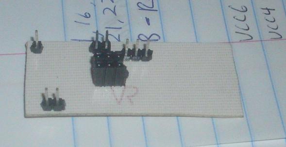
There you have it, 3 led's (Pulse, Error, Data?) Schematic was figured from the Burning the Sanguino Bootloader using Arduino as ISP page.  LED's are dead bugged on the header, not sure if you even need the cap. just plug in the 2 headers, the 6 pin ISP plug and burn away!

Seems to work so far, Tried it on my other arduino, not really extensive testing, but seems to work.I'd like to make a couple pcb's for various chips with the 6 pin ISP header on them, but that's all for now.

UPDATE:
Just built a second one, decided to move the ground from the power side to the io pin side, that allows selection of 5v or 3.3v on the VCC wire. or you can leave it disconnected if your target is self powered.