Saturday, October 27, 2012

Parallax 7345 SMPS Repair Tips

I started this as a reply in the Parallax 7345 RV Power Converter (SMPS) post. It quickly grew to the point I decided to tidy it up and make a new post out of it. Most of the specific info is for the Parallax unit though it may apply to other SMPS's.

Most of what I know about SMPS repair comes from reading: http://www.repairfaq.org/sam/smpsfaq.htm If you intend to work on a SMPS I strongly suggest reading and digesting the contents of it first.

Possible Problem Areas

Quick Disclaimer or "Safety Third":
Be very careful! There can be potentially lethal voltages all over the board even when disconnected. At least one heatsink is live! Proceed at your own risk!

Again, be careful, It's hard to diagnose a SMPS without powering it up. Usually a isolation transformer is used. I've toyed with the idea of using an inverter or generator for this. Basically you don't want the neutral tied to ground, you want it floating, then it's only dangerous between the line and neutral rather than line and ground (that you're standing on). All household / shore  power is referenced to ground at some point.  Depending on the wiring of your generator it may or may not be. I'm not sure how to advise you on this, no matter what you do there is a risk. Try to minimize it.

Check the obvious and make sure the problem lies inside the unit.
That said, I'd follow the power through the unit as much as possible. Start where the 120v line connects, I've spent hours searching boards for a problem only to find it wasn't powered to start with. make sure you have 120v going into the board from your generator / line connection before disassembling the unit.

After you can disconnect power, let it sit for a couple hours then disassemble it. Still be careful what you touch, use the one-handed method until you get the board out. turn it over and check the voltage across the two big caps, it should have bled off, but could be over 150VDC (I don't recall the voltage spec on them, assume it's fairly close to it). If they are zero (or at least below 20V) check the continuity from each power-in line to the bridge rectifier (just after the MOV, Square thing with a heatsink) it should read almost zero ohms (if it's several thousand your problem lies here).

Always look for obvious damage,burnt components, etc. 
Sometimes a burnt component is caused by a faulty but perfectly good looking component, so don't assume you found it, you may replace it only to have it go again. (A failed triac on a Maytag Neptune washing machine will destroy a resistor, replace the resistor and it will destroy it again, replace both and you can wash clothes)


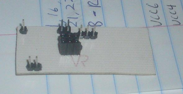
That's as far as I got on this one the problem was rather obvious, so I'm out of specific information on it. As I noted it's basically a big smps, The document at the beginning of this post should help you with the basic operation. I marked some things on the above image, you may need to check how to actually test these, but hopefully it will give you a start. As always Google is you friend, just looking for more generic SMPS info than specific Parallax info should help.

These are worth checking, roughly ordered from most likely to least (imho):
  1. Bad Capacitors, look for bulged , burst or leaking caps, they cause all kinds of headaches
  2. Output resistors. You can see these have been really hot, but are working fine on this one. However if one failed I'll bet the rest would go within seconds or the output would drop dramatically. They should be a low ohm value(0-1R). 
  3. Switcher Mosfet(s) - handles all the power, it should switch on and off really fast (100khz to several mhz, depending on design) this is connected to one of those big heatsinks, probably the live one.
  4. Logic / Startup power. I might be off the mark with this, but I think without this resistor the unit will not start. It requires some power to get thinks going, I think it comes from here. Not sure of value, but shouldn't be open and probably fairly high(100K+?).
  5. Bridge rectifier - if this goes you will get low(or no) voltage on the caps, unit may not start.
  6. The logic section, the most complicated part of the system. Controls the whole thing, depending what's wrong it may be un-repairable (bad microcontroller, even with a new micro you won't have the firmware) or could be something replaceable (op-amp, pwm controller, etc.) I put this last because I know of one that survived 240V on the input, so I assume it's pretty rugged.


Thursday, October 18, 2012

Lessons in "Confirming the problem".

Canon MF8350Cdn Printer
I just carried my new (to me) color laser printer from it's previous home in the closet up to my lab. Of course I want to test it out, and I just got a laminator (for PCB fab) so I printed out some cheat-sheet type cards to laminate. They all went fine until the last one (vi/vim) came out funny. The magenta was misaligned by a lot! I did a cleaning and several calibrations and it was still off. I thought I'd broke it. Or at least needed new cartridges for sure now. (it has been complaining about the magenta and cyan cartridges) I tore the magenta cartridge apart and found nothing unusual. I printed about 6 of these through the process, trying different things and was about to give up when it occurred to me:

The other pages printed fine, it's just this one. 

Scan of bad print
 

It was a .gif file, but it looked perfect on the computer. I printed a photograph of my dog. (Yes, I have more pictures of her than anyone else, so sue me) It came out perfect. 

I hunted around and found the vi/vim cheat sheet in pdf format. It also printed perfect. The Morale?
Always start with the last thing you changed, for me it was I was printing a different file.  Oh, yea, always Confirm the problem lies where you think before you start tearing stuff apart. 
Scan of good print
 

Kindle Fire Problems (that weren't)
The above lesson applies to the time I thought my Kindle Fire was dead, it just shut off and wouldn't turn back on. I had 70% battery, so it couldn’t be that could it? I couldn’t plug it in that night and as a result didn't sleep very well. Fortunately the next morning I plugged it in and it booted right up. Seems something hung and the battery monitor didn't update.

My Dad's Kindle Fire had a different problem. I charge mine frequently and as a result it seldom goes dead on me. Dad appears to waits until it dies before charging it. The problem? When he turns it back on some of his apps don't work. It acts like the apps are corrupted and it tells you to re-download them from the app store. That is a real pain since with no internet out here at the moment it requires a trip to the library or Lowes to do. The last time it happened we discussed returning it, as something must be wrong with it. Then he said he had noticed it would start working again a few minutes after getting a connection, no re-downloading needed. Hmm, sounds more like a “feature” than a bad memory module. Then I realized the time as wrong, I checked the date and it was back in 1999. I set the date and time manually and it works again! Among other things it updates the date and time automatically from the internet, as long as the battery is charged it keeps ticking, but if it goes completely dead it resets. If it connects as soon as it turns back on you'd never know, but out here with no internet it can't.

Tuesday, October 16, 2012

AVR Dragon Jumpers - ISP for Atmega 168/328/etc

I've been trying my hand at etching pcb's lately. As a result I needed to burn a bootloader on a Atmega 328 and I didn't put a ISP header on my target board. I really need to get in the habit of doing that. Usually I just stick it in my dragon, connect it up with a bunch of jumpers and burn it.

A while back I saw someone had made a whole set of boards for this purpose. You just plugged in the board and never get a wire crossed again! I made a brief search for them but couldn't find anything useful (schematic, pcb layouts, etc). So I made my own. So far I have made the ISP for the 168/328. Sometime I will make the HVPP for these and both for the 644/1284.

You may notice that I have a mix of male and female headers. When I got my dragon I put mostly female headers on (excluding JTAG and ISP) so I could use normal jumpers rather than special female ones. I still think it was a good idea, but most people use all male headers, so the board could use all females.

I only put the used headers for ease of use and cost control. For soldering I put all the headers in place on the dragon then added the board. It keeps everything perfectly aligned.


Etch-resist was a laser printer transfer, cupric chloride etch solution. I'll do a post on that whole process later.


I intended to attach the KiCAD Schematic and PCB file here, but I can't see how to do that (might not be possible), so I posted it over on TryThisTv.com